The Lumina LSC-400 controller provides an input for the trigger generated by the fMRI scanner. The trigger is then passed through to the serial port and Accessory Connector. This allows an application program such as MEDx or SuperLab to synchronize the presentation of a trial with the start of a scan.
The scanner trigger input built into the Lumina controller features is designed for maximum flexibility and safety. Internally, this input protects the scanner using built-in optical isolation. This literally consists of a tiny light and lightsensor pair, and prevents any electricity from flowing back and forth between the Lumina controller and scanner.
It is possible to disable the optical isolation using a pair of switches on the bottom of the Lumina enclosure. Cedrus recommends that the optical isolation be always ON whenever possible. The only time you will need to turn it off is when the MRI scanner trigger is already optically isolated (it is not possible to have two optical isolation “switches” in series).
When optical isolation is OFF, the Lumina controller accepts a differential voltage signal. Due to the nature of this signal and its lack of a reference voltage, it is quite possible that the Trigger light on the top panel (shown in the picture) might work in reverse, i.e. be ON when there is no trigger and OFF when a trigger is detected. This can be changed using the XID Control Panel program.
When shipped, Lumina scanner trigger input can detect signals with a minimum duration of 1 millisecond, suitable for GE scanners. On the LSC-400B controllers (not the original LSC-400 model), this can be changed to make the controller detect pulses as short as 10 microseconds, suitable for Siemens and other MRI scanners.
Important: when detecting pulses that short (i.e. in the 10 microseconds range), the Lumina controller’s serial port will not work when the Mode is set to “Lumina”. This is because when in Lumina / XID mode, 6 bytes are sent on the onset of the trigger, and another 6 bytes on the offset. A combination of the microprocessor’s speed and serial port speed limitations prevent the controller from producing output this fast.
To make the LSC-400B controller detect short trigger signals:
1 – Unplug everything that is connected to the back of the controller, e.g. AC adapter cable, trigger cable, or serial port cable.
2 – On the right side of the controller (the side where the power switch is located), unscrew completely any three of the four screws.
3 – Turn the fourth screw a quarter or half turn counterclockwise, just enough to loosen it. You should now be able to rotate the side cover away in order to see inside the controller. Be careful not to touch any of the electronic components inside.
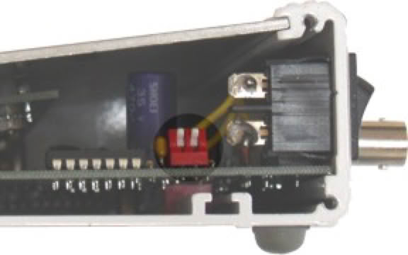
4 – You will see two small white switches (called DIP switches) in a red block. When shipped, the position of the switches is Up (open).
5 – To make the LSC-400B controller detect short trigger signals, move both DIP switches to the Down (closed) position.
6 – Close the side cover.
When input is optically isolated (via DIP switches on the bottom), the input must be driven over 1.5 volts while sourcing up to 5 mA. When input is not optically isolated, the input must be driven below 1 volt while sinking up to 4 mA.
The trigger input in the Lumina controller uses a BNC connector. This is a connector commonly used for connecting television antennas and is readily available in stores such as Best Buy or Home Dept. Cables usually come in two “impedance” choices: 50 ohm (also written 50Ω) or 75 ohm. The impedance is irrelevant in the case of the Lumina controller.
With GE scanners, the scanner trigger might be using a DB9 connector, in which case you will need a specialty trigger cable. Cedrus offers them in 15 foot and 90 foot lengths.
For Siemens scanners, the scanner trigger typically uses an optical cable. For this, you will need an optical trigger adapter.
Last revision: April 23, 2017
PRODUCTS
SUPPORT
STAY IN TOUCH
© Copyright 2026 Cedrus Corporation, P.O. Box 6309, San Pedro, CA 90734 - USA
Phone: +1-310-548-9595. Send us an email
qwerasdf