It is a common requirement to want to mark the onset of visual stimuli. This can be done by sending event markers via USB from the stimulus presentation computer, but you can also have StimTracker detect and mark the onset of visual stimuli directly. This requires some work but offers two advantages: one, it can be more accurate depending on which stimulus presentation software you are using, and two, it is software-independent.
The vast majority of experiments use a white or a black background; StimTracker ships with two light sensors, one in black and the other in white. This is intended to minimize distractions to the participant.
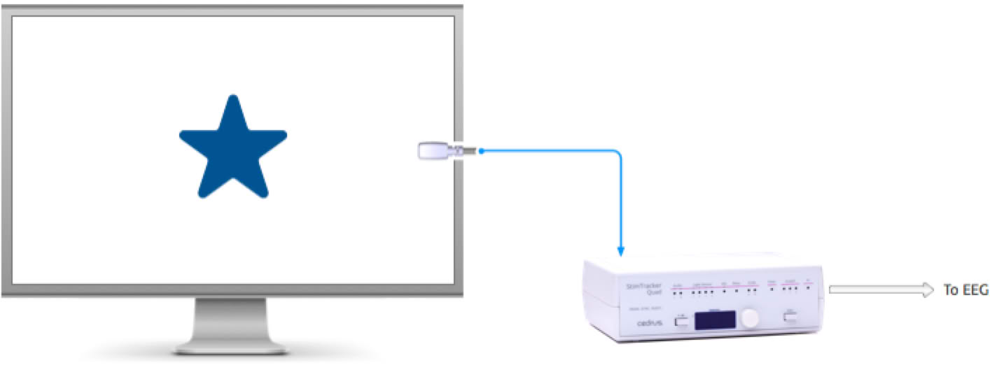
Placing the light sensor right over the stimulus would likely distract the participant. When preparing the trial, it is recommended that you also display a square or a circle near the edge of the screen. The circle needs to be only about 4 or 5 millimeters in diameter:
Once the trial is setup correctly and you are satisfied with the location of the marker circle on the monitor, peel the self-sticking tape off the light sensor and attach it to the monitor. It is recommended that the light sensor completely cover the circle in order to avoid distracting the participant.
See Using the Front Panel for information on setting the threshold. StimTracker Duo can detect up to 2 light sensors and StimTracker Quad up to 4 light sensors. You can set the thresholds independently for each sensor.
Here are a few tips:
The threshold value displayed in StimTracker ranges from 0 to 100, where 100 is most sensitive.
For StimTracker to mark the onset of a visual stimulus accurately, the light sensor patch must appear at the same time as the stimulus.
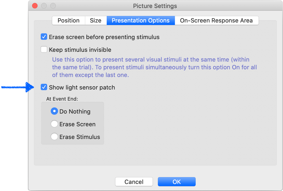
If you are using SuperLab 5 or later, there is a built-in feature to support this. When editing a stimulus in the Event Editor, select the Stimulus tab and click on the Settings… button; a dialog appears:
In this dialog, select the Presentation Options tab and enable the Show light sensor patch checkbox.
You can change the size, position, and color of the light sensor patch by selecting Options from the Experiment menu. In the dialog that appear, select “Sensor Patch Settings”. These settings apply to the entire experiment.
The most common application is to use m-pod. m-pod takes the multiplexed signals that StimTracker delivers and converts it into TTL output. By default, the output is “reflective”. This means that if the stimulus is on the screen for, say, 400ms, the width of the TTL output pulse will also be 400ms. It is possible to change this behavior so that a shorter pulse is delivered on onset and another one is delivered on offset.
StimTracker can also deliver time-stamped event marker information via USB; this is turned off by default but you can easily enable it.
On StimTracker Quad model only, event markers are also delivered via the “TTL Output” connector. Unlike with m-pod, output on this connector is always in “reflective” mode and cannot be changed.
The Microphone input on the back can be used as a fourth light sensor input. You can switch the input from microphone to a fourth light sensor using StimTracker’s front panel.
The Microphone input uses a 3.5mm jack. You will also need a 3.5mm male-to-2.5mm female adapter. This needs to be a stereo type even though the light sensor plug is a mono type.
The light sensor inputs on StimTracker Duo and Quad are capable of handling an external switch or receiving a TTL signal from another computer or I/O card; see Using an External Input Source.
Last Revision: Sep 17, 2021

PRODUCTS
SUPPORT
STAY IN TOUCH
© Copyright 2026 Cedrus Corporation, P.O. Box 6309, San Pedro, CA 90734 - USA
Phone: +1-310-548-9595. Send us an email
qwerasdf