The output signals that StimTracker makes available on the dual DB25 connectors on the back are:
•
Event markers sent by the computer via USB (8 bits)
•
4 lightsensor outputs
•
3 audio outputs (left and right channel, plus one OR’d output)
•
Voice key output (microphone)
•
6 TTL outputs, identical to the input from the TTL Input connector (RJ45)
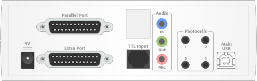
Internally, StimTracker has two voltage regulators. One is for StimTracker’s internal use. The other is solely for use by external circuits that may be plugged to the back. It provides 5 volts, up to 300 mA, and provides short circuit protection.
Here are the pin assignments for StimTracker’s top connector, designated as Parallel Port. This connector emulates a PC’s parallel port and can be connected directly to EEG/ERP devices and other peripherals that have a PC compatible parallel port. It cannot be connected directly to a PC without a signal adapter board.
•
Voice key (microphone) output is available on this connector and on the bottom Extra Port connector as well. The only difference is that output on this connector has a current limiting resistor.
•
The “TTL input” lines are identical and wired directly to the input from the TTL Input connector. They are active low. Any input detected on these lines will be converted to active high and sent to the “TTL output” lines on the Extra Port connector.
Pin
StimTracker Signal
1
N/C
2
Light sensor 1
3
Light sensor 2
4
TTL “OR” output (see note 1 below)
5
Audio “OR” (left or right, see note 2 below)
6
Microphone (current limited)
7
Event marker bit 0
8
Event marker bit 1
9
Event marker bit 2
10
RJ45/TTL input line 4
11
RJ45/TTL input line 5
12
RJ45/TTL input line 3
13
RJ45/TTL input line 2
Pin
14
15
16
17
18
19
20
21
22
23
24
25
StimTracker Signal
N/C
RJ45/TTL input line 1
N/C
N/C
Ground
Ground
Ground
Ground
Ground
Ground
Ground
Ground
Note 1: Pin 4 delivers an OR’d TTL output, i.e. the line is enabled when input is detected on any of TTL line 1, TTL line 2, TTL line 3, TTL line 4, TTL line 5, or TTL line 6.
Note 2: Pin 5 delivers an OR’d audio output, i.e. the line is enabled when the volume rises above the preset threshold on either the left audio channel or the right audio channel.
Here are the pin assignments for StimTracker’s bottom connector, labeled as Extra Port.
•
The “TTL output” lines correspond to the TTL Input lines but inverted from active low to active high, 5V signal.
•
The Extra TTL input lines are not connected to the main board — only to an internal expansion connector.
Pin
StimTracker Signal
1
N/C
2
+5 volts
3
TTL output line 1
4
TTL output line 3
5
TTL output line 5
6
Light sensor 3
7
Event marker bit 7
8
Event marker bit 5
9
Event marker bit 3
10
Extra TTL input line 1
11
Audio, right channel
12
Ground
13
Ground
Pin
14
15
16
17
18
19
20
21
22
23
24
25
StimTracker Signal
+5 volts
+5 volts
TTL output line 2
TTL output line 4
TTL output line 6
Light sensor 4
Event marker bit 6
Event marker bit 4
Extra TTL input line 2
Audio, left channel
Microphone
Ground
Last revision: February 11, 2013
PRODUCTS
SUPPORT
STAY IN TOUCH
© Copyright 2026 Cedrus Corporation, P.O. Box 6309, San Pedro, CA 90734 - USA
Phone: +1-310-548-9595. Send us an email
qwerasdf