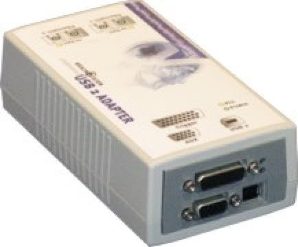
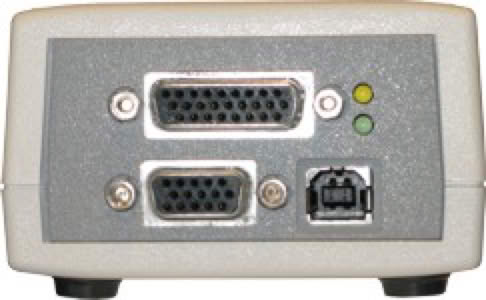
Cedrus manufactures a StimTracker adapter board that makes it possible to interface with Brain Products’ USB2 interface using a standard DB26 cable. This document describes the signals that the adapter board makes available to USB2.
Ground is on DB26 pins 1 and 22. See also the note in Using StimTracker about the rate at which the LEDs flash in StimTracker’s front panel.
Unfortunately, a design error was discovered after StimTracker shipped: the right and left channels are swapped. When StimTracker detects input on the left channel, it will incorrectly flash the “R” LED instead of the “L” one, and vice versa. The event markers that are produced are swapped as well.
Back to StimTracker Support main page ►
Last Revision: May 1, 2020
StimTracker Signal
Seen by BrainVision Recorder as
Event marker bit 0
Bit 0
Bit 1
Event marker bit 1
Event marker bit 2
Bit 2
Bit 3
Event marker bit 3
Event marker bit 4
Bit 4
Bit 5
Light sensor 1
Light sensor 2
Bit 6
Bit 7
Audio, left channel
Audio, right channel
Bit 8
Bit 9
Microphone
TTL input, line 1
Bit 10
Bit 11
TTL input, line 2
TTL input, line 3
Bit 12
Bit 13
TTL input, line 4
TTL input, line 5
Bit 14
Bit 15
TTL input, line 6
PRODUCTS
SUPPORT
STAY IN TOUCH
© Copyright 2026 Cedrus Corporation, P.O. Box 6309, San Pedro, CA 90734 - USA
Phone: +1-310-548-9595. Send us an email
qwerasdf