Cedrus manufactures a StimTracker adapter board that makes it possible to interface with ADInstruments’ PowerLab data acquisition system using a standard DB15 cable. This document describes the signals that the adapter board makes available to PowerLab.

The cable from StimTracker’s output should be connected to PowerLab’s Digital Input connector. StimTracker is compatible with all PowerLab models except:
The digital input number is as seen in LabChart. You will need the decimal value for using the “Digital byte” feature; more on that below. See also the note in Using StimTracker about the rate at which the LEDs flash in StimTracker’s front panel.
StimTracker Signal
Light sensor 1
Light sensor 2
TTL input
Audio L+R
Microphone
Event marker bit 0
Event marker bit 1
Event marker bit 2
Digital Bit
Decimal Value
Comments
StimTracker will send output to LabChart’s digital input no. 3 when it detects input on any of the six TTL/digital input lines.
StimTracker will send output to LabChart’s digital input no. 4 when the volume rises above the preset threshold on either the left audio channel or the right audio channel.
1
1
2
2
3
4
4
8
5
16
6
32
7
64
8
128
These instructions apply to LabChart version 8.1.5; they will also work with earlier versions of LabChart for Windows, but you will need version 8.1.5 or later of LabChart for Mac.
1.
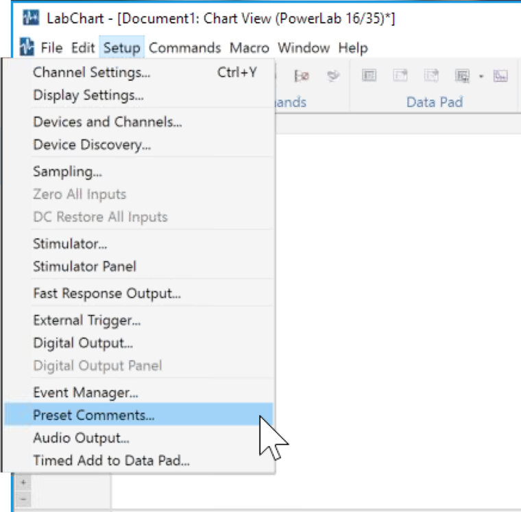
Click on the Setup menu and choose Preset Comments….
2.
3.
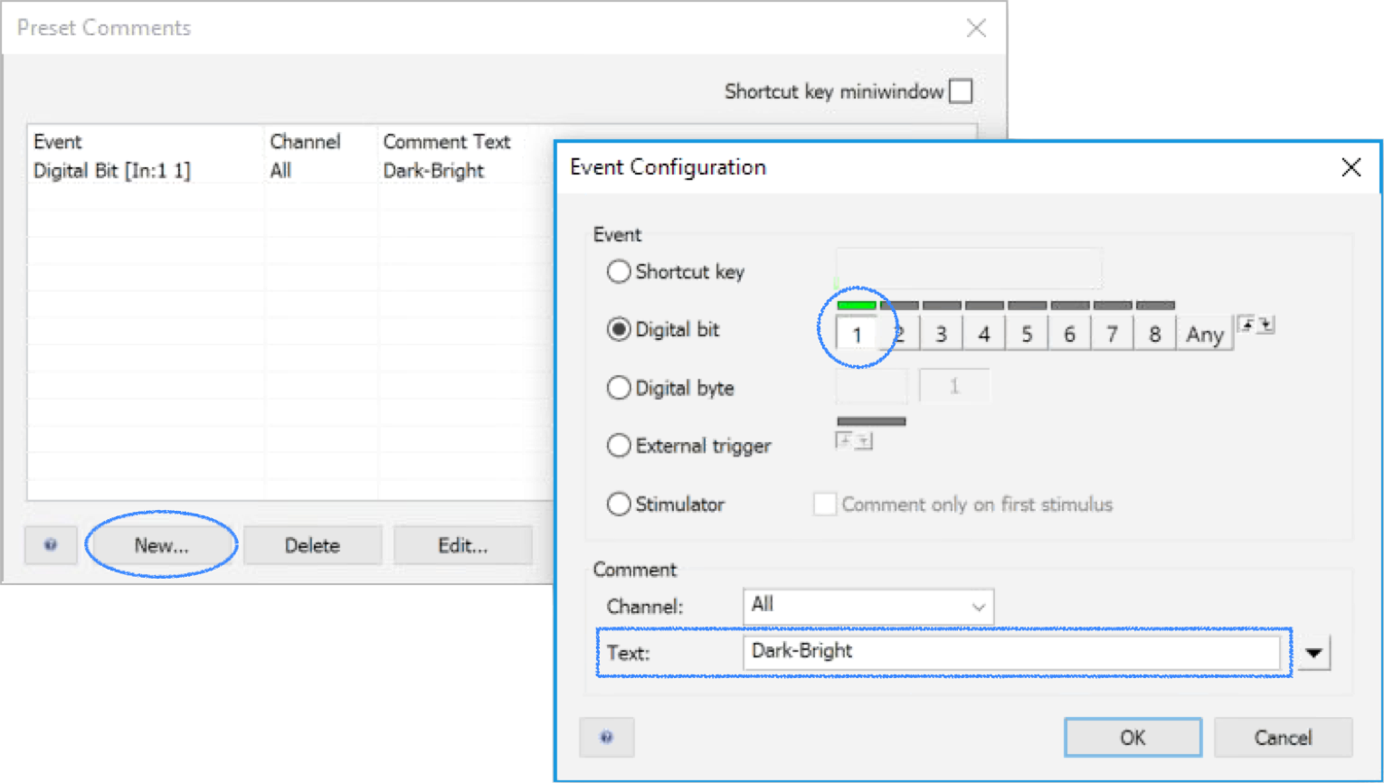
The Preset Comments dialog appears. Click on the New… button; an Event Configuration dialog appears.
As an example, let’s setup a preset comment for light sensor 1 by choosing the Digital bit radio button. Click button “1” to select digital bit 1, shown circled in the screen snapshot below. If you have light sensor 1 plugged into StimTracker, the green bar above digital bit 1 will light up every time the light sensor detects light, providing real-time feedback.
4.
5.
6.
Give this preset comment a name, e.g. “Dark-Bright”.
Click OK to close the Event Configuration dialog. The “Dark-Bright” event will now show up in the Preset Comments dialog.
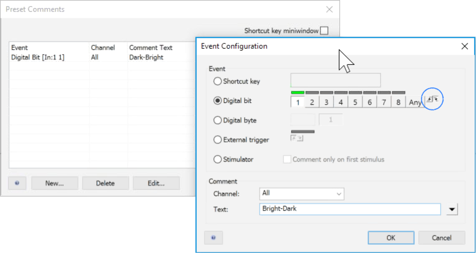
The steps completed thus far will have LabChart detect and record the “onset” of light, i.e. when the light sensor goes from dark to bright. An additional preset comment is needed to detect the offset of light, that is, going from bright back to dark. Click on the New… button again in the Preset Comments to bring up the Event Configuration dialog again:
7.
8.
9.
10.
As we did earlier, click button “1” to select digital bit 1 and give this event a name, “Bright-Dark”.
To detect the offset instead of onset, there are two small buttons on the right side of the dialog, circled in the screenshot above. Click on the arrow pointing down.
Click OK to close the Event Configuration dialog, and OK again to close the Preset Comments dialog.
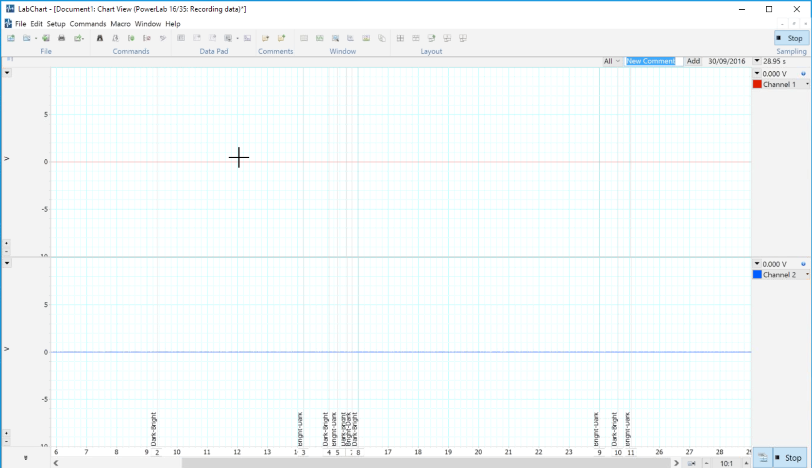
Back in the main window, you can test that the preset comments are working correctly by starting the recording and then covering and uncovering the light sensor with your finger. You will see “Dark-Bright” and “Bright-Dark” comments on the bottom of the window along with corresponding vertical lines:
To setup preset comments for other types of events, simply click on a different “Digital bit” button in Step 3. In the section above, The Signals, the table lists the input numbers, e.g. click on button “4” in the Event Configuration dialog to detect onset and/or offset of audio.
When receiving event codes via USB, StimTracker passes three bits of data out to PowerLab and LabChart. Researchers typically want to interpret the data in one of two ways:
To examine the individual data bits as flags, follow the same instructions as above. But to look at them in combination as a value, a slightly different approach is needed:
1.
As before, click on the Setup menu and choose Preset Comments…. When the Preset Comments dialog appears, click on the New… button to bring up the Event Configuration dialog.
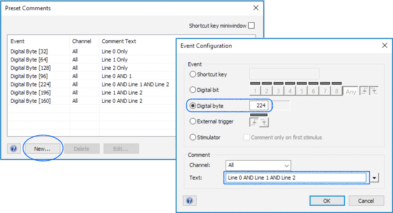
2.
Select the Digital byte radio button and enter the byte value. In the example above, we create a preset comment for one all three event marker bits are ON at the same time. As you can see in The Signals table above, the decimal values for three event marker bits are 32, 64, and 128, which add up to 224.
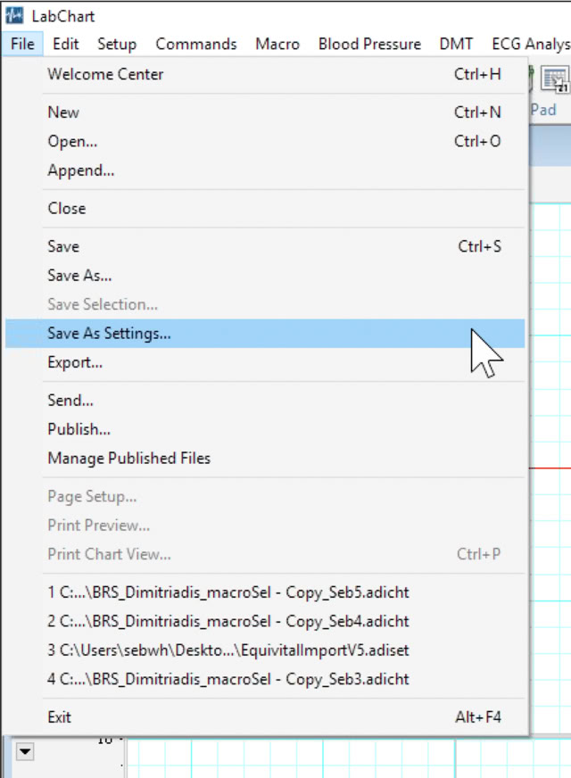
ADInstruments recommends that you create a preset comment for every possible combination, as shown in the right dialog in the screenshot above. This would simplify your data analysis later on. If multiple experiments will be using the same preset comments, you can save time by saving the settings into a file by clicking on the File menu in LabChart and choosing Save As Settings…. This will produce a file with a .adiset extension.
Last Revision: Jan 18, 2017
PRODUCTS
SUPPORT
STAY IN TOUCH
© Copyright 2026 Cedrus Corporation, P.O. Box 6309, San Pedro, CA 90734 - USA
Phone: +1-310-548-9595. Send us an email
qwerasdf