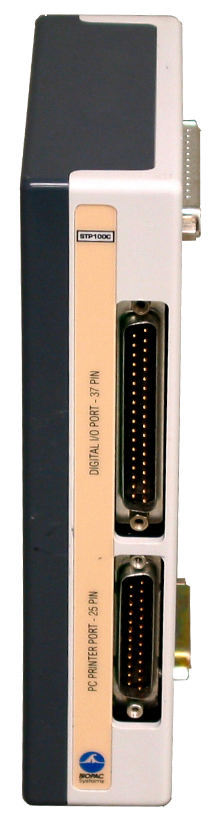
m-pod for Biopac STP100C plugs to the 37-pin Digital I/O Port connector on the STP100C module via an included blue ribbon cable. This document describes the signals that m-podmakes available to STP100C.
Please note that the STP100C also has a DB25 connector but it is not compatible with the DB25 connector on the MP35 and MP36. Connecting “m-pod for Biopac MP36” to the STP100C will not work.
Setting up AcqKnowledge to work with m-pod is straightforward. The screen snapshots below were taken using AcqKnowledge 4.2.
1.
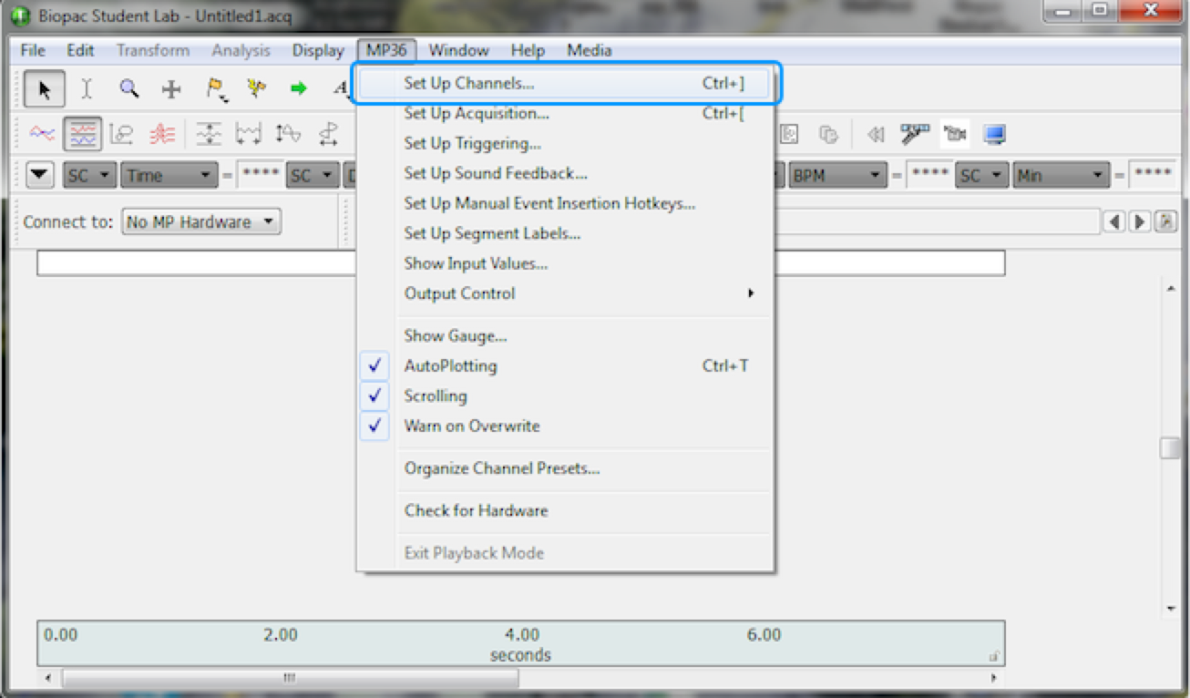
Click on the MP150 menu and choose Set Up Channels….
2.
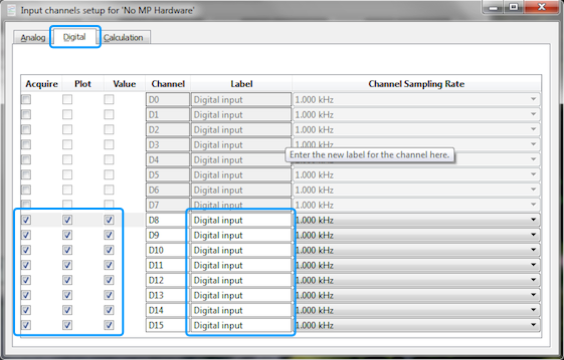
The “Input channels setup” dialog appears. Click on the Digital tab.
3.
For channels D8 to D15, enable all checkboxes for each of the Acquire, Plot, and Value columns.
4.
Optionally, you can also rename the labels.
Close the “Input channels setup” dialog and click on “Start”.
The channel number in the table is as seen in the AcqKnowledge software. Ground is on DB37 connector pins 19 and 21.
When Connected to a Riponda or RB-x40 Response Pad
Trigger Value
For
D8
USB bit 0
Key press 1
OR
D9
USB bit 1
Key press 2
OR
D10
USB bit 2
Key press 3
OR
D11
USB bit 3
Key press 4
OR
D12
USB bit 4
Key press 5
OR
D13
USB bit 5
Key press 6
OR
D14
USB bit 6
Key press 7
OR
D15
USB bit 7
Key press 8
Light sensor
OR
OR
Note:
When used with a Lumina 3G controller, the same info applies, with the difference that key presses 5 through 8 correspond to keys 1 through 4 on “Response Pad 2”.
When Connected to StimTracker
Trigger Value
For
Notes
D8
USB bit 0
Light sensor 4
Quad model only
OR
D9
USB bit 1
Light sensor 3
Quad model only
OR
D10
USB bit 2
Light sensor 2
OR
D11
USB bit 3
Voice key / mic
Quad model only
OR
D12
USB bit 4
Any participant key press
OR
D13
USB bit 5
Audio – left
OR
D14
USB bit 6
Audio – right
OR
D15
USB bit 7
Light sensor 1
OR
m-pod contains a powerful microprocessor that can reassign any input signal to any output line, and without any significant delay. It can also assign multiple signals to the same output line.
The tables above describe the factory default. If your experiment or lab setup requires different output, Cedrus provides a free utility for configuring your m-pod. After you use it, your configuration is saved to flash memory so that it’s remembered even after you power off m-pod.

Last Revision: June 27, 2018
PRODUCTS
SUPPORT
STAY IN TOUCH
© Copyright 2026 Cedrus Corporation, P.O. Box 6309, San Pedro, CA 90734 - USA
Phone: +1-310-548-9595. Send us an email
qwerasdf