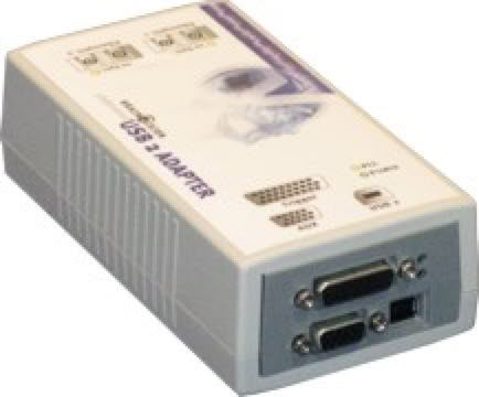
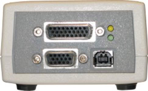
m-pod for Brain Products USB2 plugs directly into the Brain Products’ USB2 interface:
You do not really need to do anything in Recorder in order to see event makers. They are displayed at the bottom of the screen, e.g. S32, S64, and so forth:
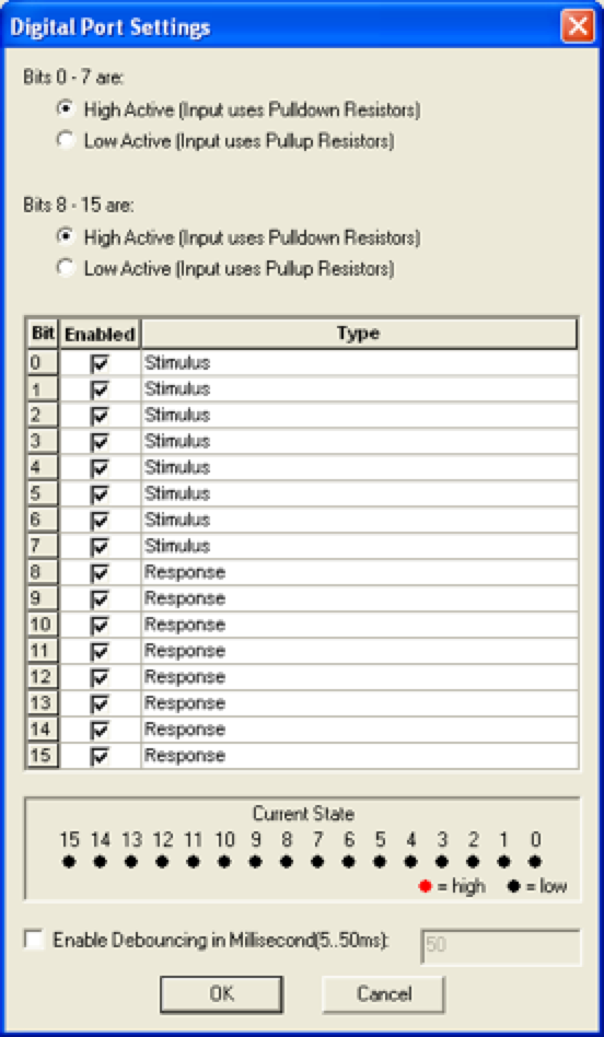
However, you may find that adjusting some settings can make your data analysis easier later on. To do so, click on the Amplifier menu and choose Digital Port Settings…. Recorder displays the following dialog:
In the table, click on the “Type” column of the relevant row to rename, e.g. rename “Stimulus” to “Light sensor”. Recorder will then display an “L” prefix instead of “S” when it detects a light sensor event marker. See Recorder’s manual for more information.
Ground is on DB26 pins 1 and 22. The leftmost column shows the bit numbers as seen by BrainVision Recorder:
m-pod contains a powerful microprocessor that can reassign any input signal to any output line, and without any significant delay. It can also assign multiple signals to the same output line.
The tables above describe the factory default. If your experiment or lab setup requires different output, Cedrus provides a free utility for configuring your m-pod. After you use it, your configuration is saved to flash memory so that it’s remembered even after you power off m-pod.
Last Revision: July 31, 2018


When Connected to a Riponda or RB-x40 Response Pad
Seen by BV Recorder as
For
Bit 0
Key press 1
Bit 1
Key press 2
Bit 2
Key press 3
Bit 3
Key press 4
Bit 4
Key press 5
Bit 5
Key press 6
Bit 6
Key press 7
Bit 7
Key press 8
Light sensor
OR
Bit 8
USB bit 0
Bit 9
USB bit 1
Bit 10
USB bit 2
Bit 11
USB bit 3
Bit 12
USB bit 4
Bit 13
USB bit 5
Bit 14
USB bit 6
Bit 15
USB bit 7
Note:
When used with a Lumina 3G controller, the same info applies, with the difference that key presses 5 through 8 correspond to keys 1 through 4 on “Response Pad 2”.
When Connected to StimTracker
Trigger Value
For
Notes
Bit 0
Light sensor 4
Quad model only
Bit 1
Light sensor 3
Quad model only
Bit 2
Light sensor 2
Bit 3
Voice key / mic
Quad model only
Bit 4
Any participant key press
Bit 5
Audio – left
Bit 6
Audio – right
Bit 7
Light sensor 1
Bit 8
USB bit 0
Bit 9
USB bit 1
Bit 10
USB bit 2
Bit 11
USB bit 3
Bit 12
USB bit 4
Bit 13
USB bit 5
Bit 14
USB bit 6
Bit 15
USB bit 7

PRODUCTS
SUPPORT
STAY IN TOUCH
© Copyright 2026 Cedrus Corporation, P.O. Box 6309, San Pedro, CA 90734 - USA
Phone: +1-310-548-9595. Send us an email
qwerasdf