m-pod for ADI plugs directly into Digital Input connector on the back of ADInstruments’ PowerLab data acquisition systems:

The other side of m-pod connects to the computer’s USB port (cable included). m-pod for ADI is compatible with all PowerLab models except:
The digital input number is as seen in the LabChart software. You will need the decimal value for using the LabChart “Digital byte” feature. More on that below.
When Connected to a Riponda or RB-x40 Response Pad
Digital Input No.
Decimal Value
For
1
1
USB bit 0
Key press 1
OR
2
2
USB bit 1
Key press 2
OR
3
4
USB bit 2
Key press 3
OR
4
8
USB bit 3
Key press 4
OR
5
16
USB bit 4
Key press 5
OR
6
32
USB bit 5
Key press 6
OR
7
64
USB bit 6
Key press 7
OR
8
128
USB bit 7
Key press 8
Light sensor
OR
OR
Note:
When used with a Lumina 3G controller, the same info applies, with the difference that key presses 5 through 8 correspond to keys 1 through 4 on “Response Pad 2”.
When Connected to StimTracker
Digital Input No.
Decimal Value
For
Notes
1
1
USB bit 0
Light sensor 4
Quad model only
OR
2
2
USB bit 1
Light sensor 3
Quad model only
OR
3
4
USB bit 2
Light sensor 2
OR
4
8
USB bit 3
Voice key / mic
Quad model only
OR
5
16
USB bit 4
Any participant key press
OR
6
32
USB bit 5
Audio – left
OR
7
64
USB bit 6
Audio – right
OR
8
128
USB bit 7
Light sensor 1
OR

m-pod contains a powerful microprocessor that can reassign any input signal to any output line, and without any significant delay. It can also assign multiple signals to the same output line.
The tables above describe the factory default. If your experiment or lab setup requires different output, Cedrus provides a free utility for configuring your m-pod. After you use it, your configuration is saved to flash memory so that it’s remembered even you power off m-pod.
The LabChart feature that you need is called “preset comments”. It offers a few different ways to record external triggers, but only two are relevant to using m-pod. One method is called digital bit and the other is digital byte:
Note that you can use digital bits and digital bytes in the same experiment. You can describe the congruency of a trial using two input bits and note the color on another four bits — and you still have two extra bits available. We will use the two examples above to provide step-by-step instructions next.
Let’s setup two preset comments to describe a trial’s congruency. We will use digital bits 7 and 8.
These instructions apply to LabChart version 8.1.5; they will also work with earlier versions of LabChart for Windows, but you will need version 8.1.5 or later of LabChart for Mac.
1.
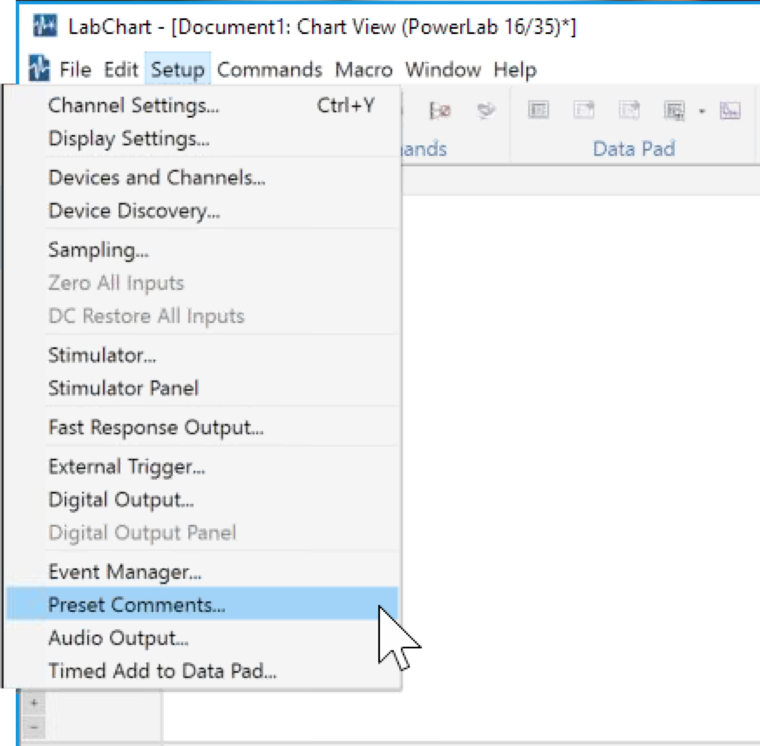
Click on the Setup menu and choose Preset Comments….
2.
3.
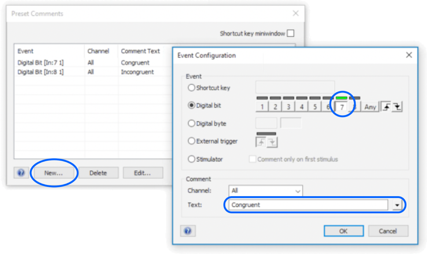
The Preset Comments dialog appears. Click on the New… button; an Event Configuration dialog appears.
Let’s setup a preset comment for trial condition “Congruent” by choosing the Digital bit radio button. Click button “7” to select digital bit 7, shown circled in the screen snapshot below. The bars about the buttons are “live”: they will light up in green when input is detected, providing real-time feedback.
4.
5.
6.
Give this preset comment a name, e.g. “Congruent”.
Repeat the steps above to create an “Incongruent” preset comment, but this time using bit 8 instead.
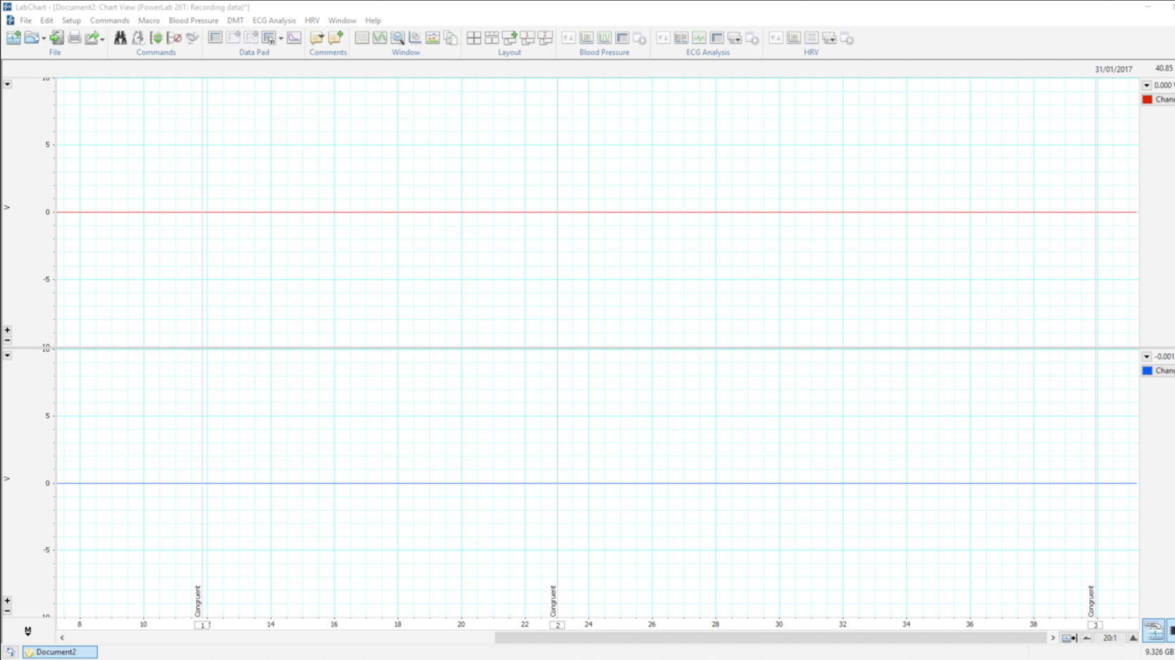
Back in the main window, you can test that the preset comments are working correctly by starting the recording, and in SuperLab, send digital output signals on lines EC6 and EC7. You will see “Congruent” and “Incongruent” comments on the bottom of the window along with corresponding vertical lines:
Now let’s setup preset comments to describe the color of the text being presented. We will use digital bits 1, 2, 3 and 4, the combination of which will allow us to provide 15 different values.
1.
As before, click on the Setup menu and choose Preset Comments…. When the Preset Comments dialog appears, click on the New… button to bring up the Event Configuration dialog.
2.
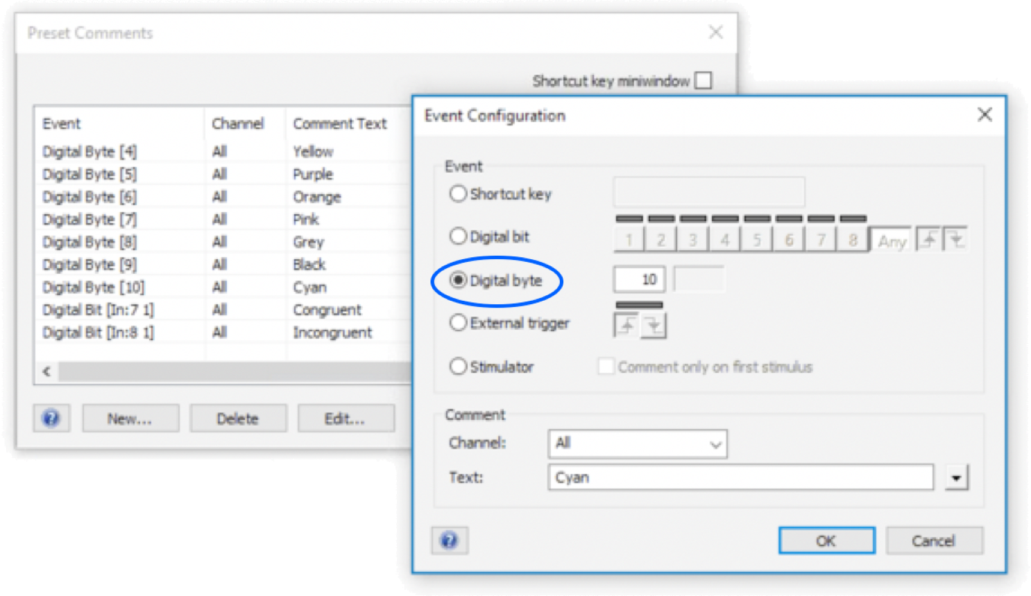
Select the Digital byte radio button.
3.
The screenshot above shows a digital value of 10 for a “Cyan”. ADInstruments advises that you create a preset comment for every value that you anticipate using.
It is possible to mix digital bits and digital byte preset comments in the same experiment, as illustrated above.
Last Revision: July 3, 2018
PRODUCTS
SUPPORT
STAY IN TOUCH
© Copyright 2026 Cedrus Corporation, P.O. Box 6309, San Pedro, CA 90734 - USA
Phone: +1-310-548-9595. Send us an email
qwerasdf