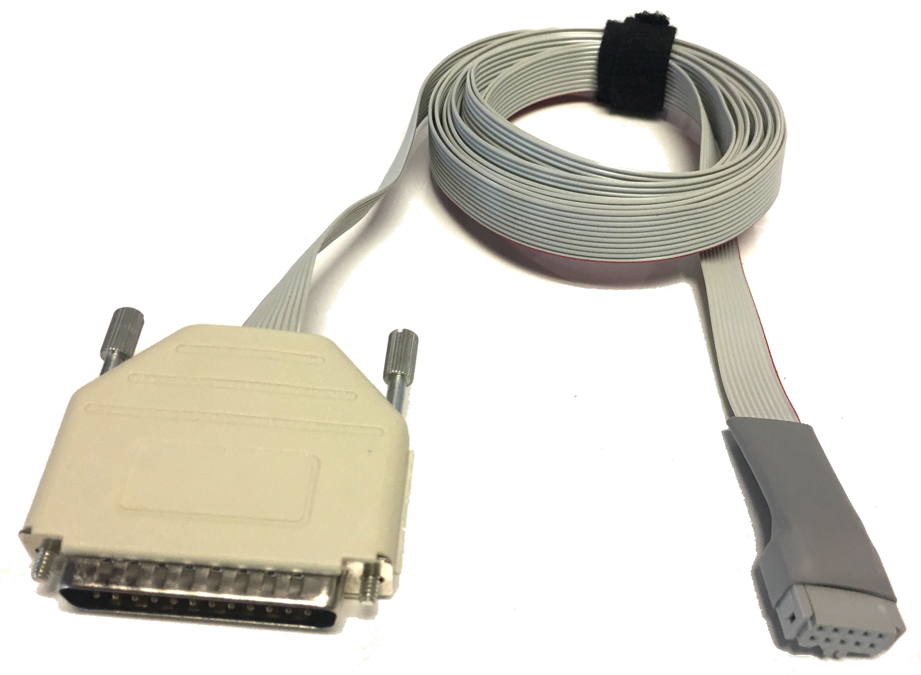
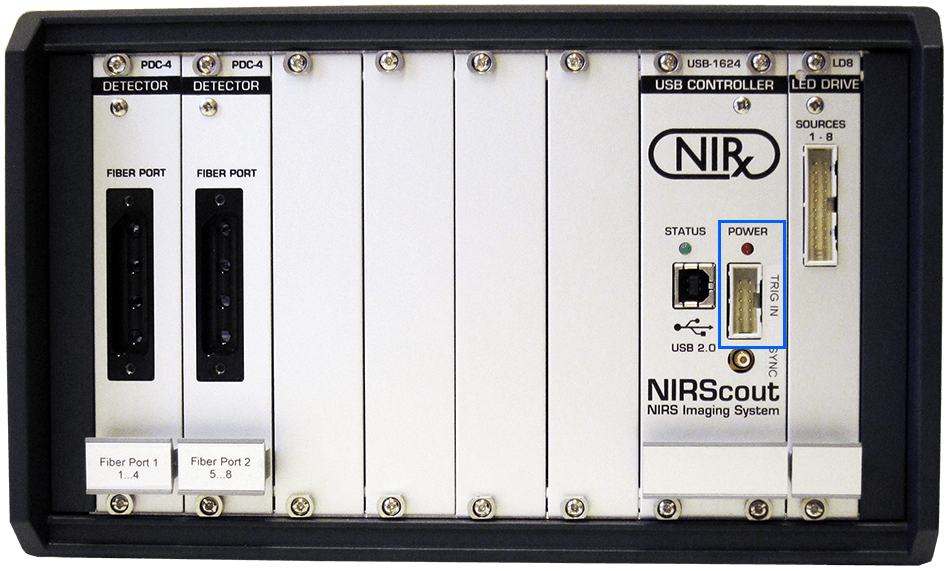
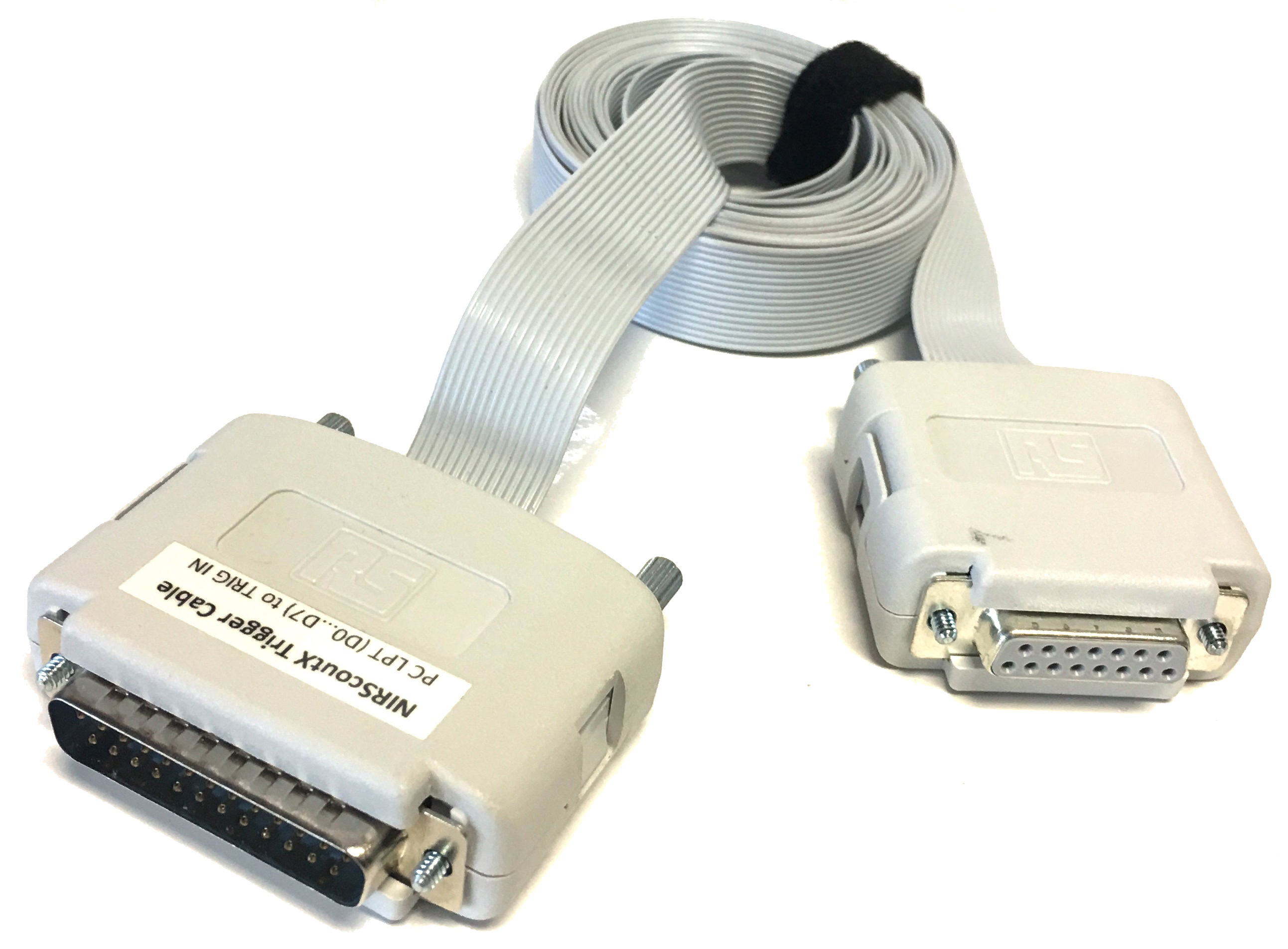
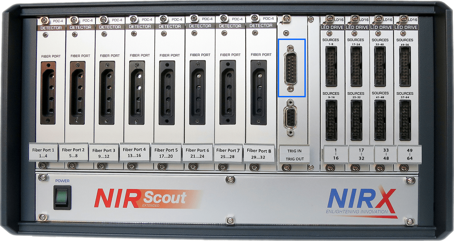
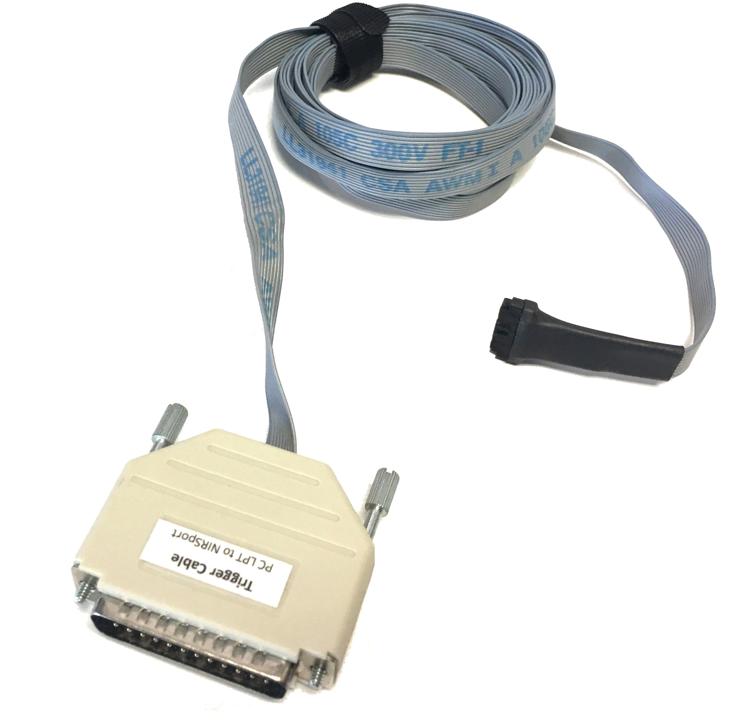
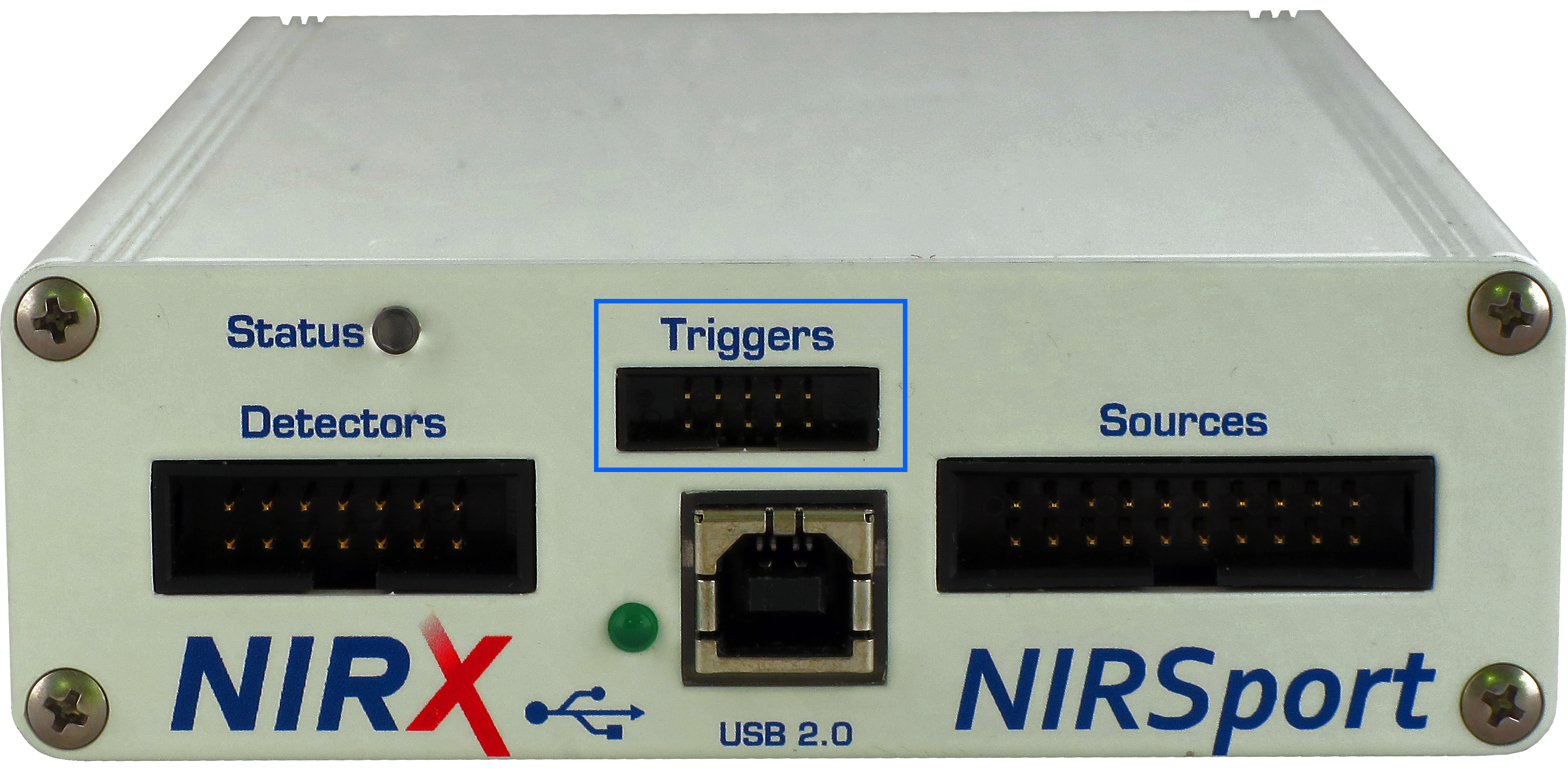
“m-pod for NIRx” delivers 8 bits of external triggers to your NIRx recorder. Depending on the model, 4 or 8 bits will be recorded. m-pod connects to an adapter cable that is included with every NIRx recorder. The other side of this adapter cable plugs into the trigger connector on the NIRx recorder, highlighted in blue in the pictures below. Click on any of them to zoom:
Model NIRScout
Models NIRScout Extended & Extended+
Model NIRSport
The other side of m-pod connects, via an included cable, to a host product like an RB response pad, StimTracker Duo or Quad, or Lumina 3G controller. The host product may require the installation of a USB driver, but m-pod itself does not require any software – just plug and go. A utility program called Xidon allows you to change pin assignments and other settings, but it is optional; more about that below.
No particular setup is necessary on the NIRx side. The NIRStar software is always looking for trigger input and displays that information in its main window. The screenshot below shows an event marker on every other input line:
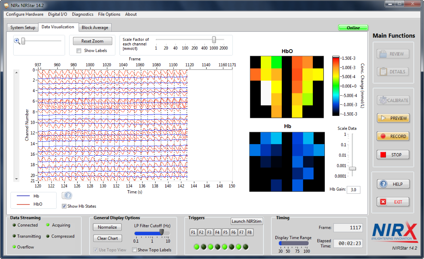
Trigger Information
Event markers that you send need to be at least 10ms long and separated by at least 100ms. Tip: you can also simulate an event marker by clicking on the F1 through F8 buttons, or pressing F1…F8 on the keyboard.
The NIRScout Extended and Extended+ models support 8 trigger bits, F1 through F8. The NIRScout Standard and NIRSport support 4 trigger bits, F1 through F4.
When Connected to a Riponda or RB-x40 Response Pad
NIRStar Receives Trigger
For
F1
USB bit 0
Key press 1
OR
F2
USB bit 1
Key press 2
OR
F3
USB bit 2
Key press 3
OR
F4
USB bit 3
Key press 4
OR
F5
USB bit 4
Key press 5
OR
F6
USB bit 5
Key press 6
OR
F7
USB bit 6
Key press 7
OR
F8
USB bit 7
Key press 8
Light sensor
OR
OR
Note:
When used with a Lumina 3G controller, the same info applies, with the difference that key presses 5 through 8 correspond to keys 1 through 4 on “Response Pad 2”.
When Connected to StimTracker
NIRStar Receives Trigger
For
Notes
F1
USB bit 0
Light sensor 4
Quad model only
OR
F2
USB bit 1
Light sensor 3
Quad model only
OR
F3
USB bit 2
Light sensor 2
OR
F4
USB bit 3
Voice key / mic
Quad model only
OR
F5
USB bit 4
Any participant key press
OR
F6
USB bit 5
Audio – left
OR
F7
USB bit 6
Audio – right
OR
F8
USB bit 7
Light sensor 1
OR
m-pod contains a powerful microprocessor that can reassign any input signal to any output line, and without any significant delay. It can also assign multiple signals to the same output line.
The tables above describe the factory default. If your experiment or lab setup requires different output, Cedrus provides a free utility for configuring your m-pod. After you use it, your configuration is saved to flash memory so that it’s remembered even after you power off m-pod.

Last Revision: Jun 25, 2018
PRODUCTS
SUPPORT
STAY IN TOUCH
© Copyright 2026 Cedrus Corporation, P.O. Box 6309, San Pedro, CA 90734 - USA
Phone: +1-310-548-9595. Send us an email
qwerasdf