The TTL Input connector on the back of StimTracker can monitor up to six digital/TTL input lines and generate event markers when the state changes on these lines. This support page provides the details.
Note: If you want to mark when the participant has response and you are using a Cedrus response, see Marking the Participant’s Response.
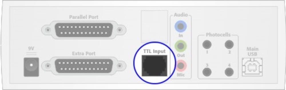
The TTL Input connector accepts six inputs. Each input line has a corresponding blue LED on the front panel, and all lines are available as outputs on the two DB25 connectors. In addition, StimTracker produces an “OR” line. That is, one output line is activated when any of the six TTL input lines is active.
Physically, the TTL Input connector uses an RJ45 jack. This is the same type of jacks used in Ethernet wiring, making it easier for find and buy matching cables in a wide variety of lengths and colors.
Please note that even though StimTracker’s TTL Input connector and the Accessory Connector on other Cedrus products use the same RJ45 connector, they do not have the same pin assignments.
The pins of the TTL Input in StimTracker were assigned in such a way to make it very easy to capture participants’ input in an experiment and forward that information to the EEG recording equipment directly, instead of through the stimulus presentation computer’s USB port. All you need is an Ethernet cable, shown as the blue line in the following diagram:
The TTL Input connector can also be used for any type of digital input. The specifications are:
•
Delay: less than 1µs from input to output
•
Voltage: 0-5V (switching threshold 2.5V with +/- 0.5V hysterisis)
•
Current: Pins pulled high internally and will source 500 µA when pulled low
None of the input lines on the TTL Input connector are debounced. The blue LED indicators on the front panel will turn On for a minimum of 200 millisecond when input is detected.
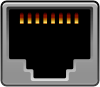
The RJ45 jack has eight pins. One is ground. Another is positive voltage. The remaining six are I/O lines. The table below describes the pin assignments. Pin 1 is the leftmost pin when you are looking at the connector.
Pin
Description
Corresponds To
1
TTL Input line 1
Accessory Connector line AC1
2
TTL Input line 2
Accessory Connector line AC2
3
TTL Input line 3
Accessory Connector line AC3
4
TTL Input line 4
Accessory Connector line AC4
5
TTL Input line 5
Accessory Connector line AC5
6
TTL Input line 6
Accessory Connector line AC6
7
+5 volt ±5%
8
Ground (rightmost pin)
Accessory Connector
Last revision: July 14, 2008
PRODUCTS
SUPPORT
STAY IN TOUCH
© Copyright 2026 Cedrus Corporation, P.O. Box 6309, San Pedro, CA 90734 - USA
Phone: +1-310-548-9595. Send us an email
qwerasdf