If you are using Net Station 4.x, please see this older support note.
Make sure that your m-pod firmware and StimTracker firmware are using version 2.2.7 or later. You can check the firmware version and update it if necessary using our free Xidon software.
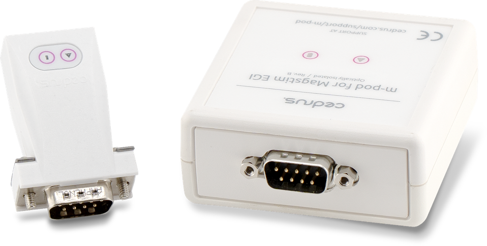
There are two versions of m-pod for EGI, revisions A and B:
If using revision A:
When using revision B:
m-pod for EGI is fitted with a DB9 connector. It is ready to plug into the GES 200 and GES 250, using the Net Amps 200. On the GES 300 and later systems, an additional “Hypertronics-to-DB9” cable is needed. EGI installations typically have this cable already, but if your does not, you can buy one from EGI or Cedrus’ store.
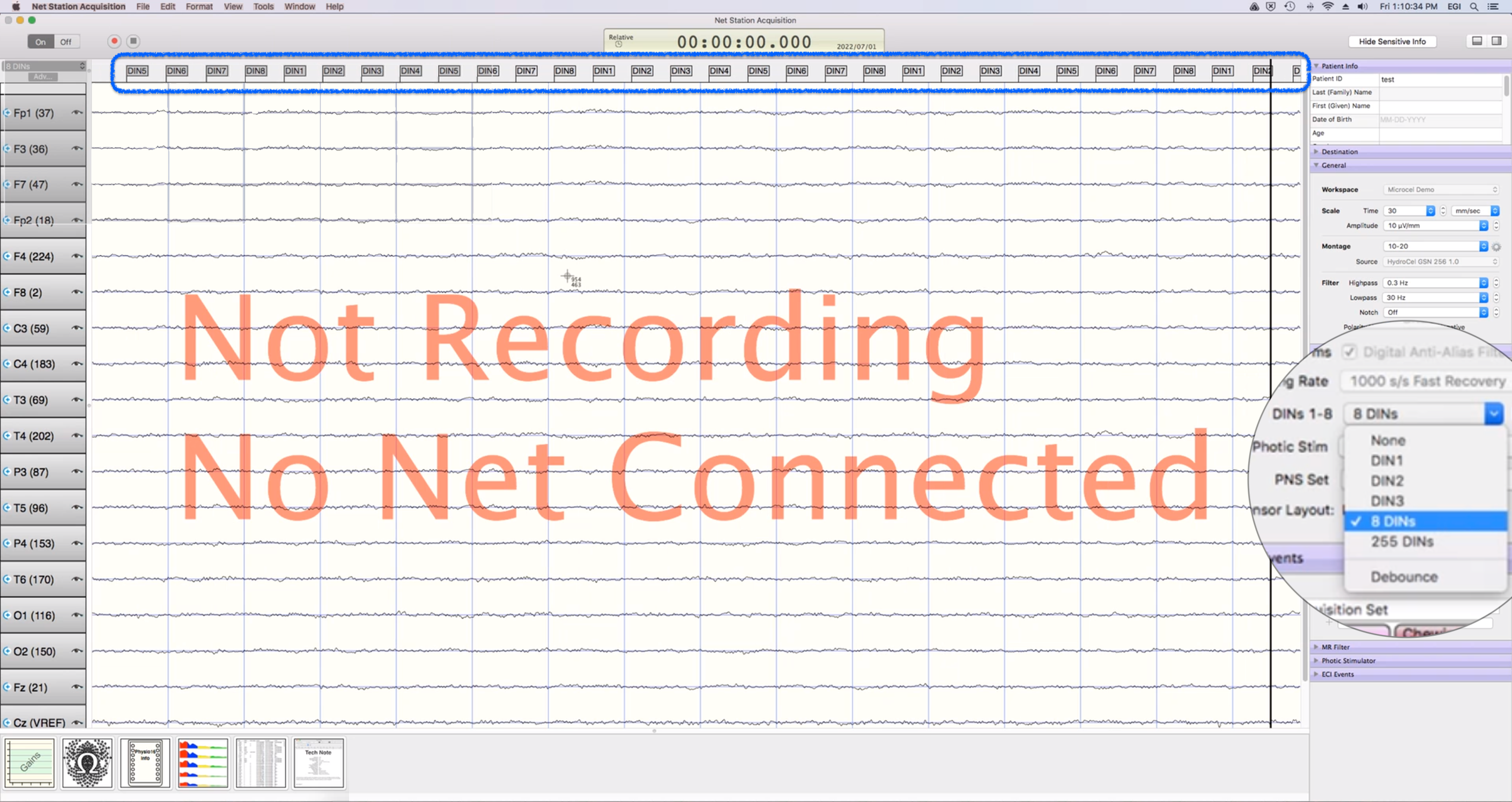
Net Station 5 can only record the onset of a signal; it cannot record the offset. For example, when using a light sensor, Net Station 5 can record when a stimulus has appeared on the screen but not when it gets masked (erased).
Setting up Net Station 5 to work with m-pod is straightforward. Make sure that the setting “DINs 1-8” on the right side is set to “8 DINs”. In the screenshot below, in the upper part of the window, you can see event markers (DINs) being received periodically.
The trigger value is as seen in the Net Station software.
When Connected to a Riponda or RB-x40 Response Pad
When Connected to StimTracker
m-pod contains a powerful microprocessor that can reassign any input signal to any output line, and without any significant delay. It can also assign multiple signals to the same output line.
The tables above describe the factory default. If your experiment or lab setup requires different output, Cedrus provides a free utility for configuring your m-pod. After you use it, your configuration is saved to flash memory so that it’s remembered even after you power off m-pod.
Last Revision: Jun 24, 2025
Trigger Value
For
DIN1
USB bit 0
Key press 1
OR
DIN2
USB bit 1
Key press 2
OR
DIN3
USB bit 2
Key press 3
OR
DIN4
USB bit 3
Key press 4
OR
DIN5
USB bit 4
Key press 5
OR
DIN6
USB bit 5
Key press 6
OR
DIN7
USB bit 6
Key press 7
OR
DIN8
USB bit 7
Key press 8
Light sensor
OR
OR
Note:
When used with a Lumina 3G controller, the same info applies, with the difference that key presses 5 through 8 correspond to keys 1 through 4 on “Response Pad 2”.
Trigger Value
For
Notes
DIN1
USB bit 0
Light sensor 4
Quad model only
OR
DIN2
USB bit 1
Light sensor 3
Quad model only
OR
DIN3
USB bit 2
Light sensor 2
OR
DIN4
USB bit 3
Voice key / mic
Quad model only
OR
DIN5
USB bit 4
Any participant key press
OR
DIN6
USB bit 5
Audio – left
OR
DIN7
USB bit 6
Audio – right
OR
DIN8
USB bit 7
Light sensor 1
OR

PRODUCTS
SUPPORT
STAY IN TOUCH
© Copyright 2026 Cedrus Corporation, P.O. Box 6309, San Pedro, CA 90734 - USA
Phone: +1-310-548-9595. Send us an email
qwerasdf